CO2 Jet Installation: The Complete Guide To Installing A Cryo System
CO2 Jet Installation Guide: Permanent & Semi-Permanent Setups | CryoFX
CO2 Jet Installation: The Complete Guide To Installing A Cryo System
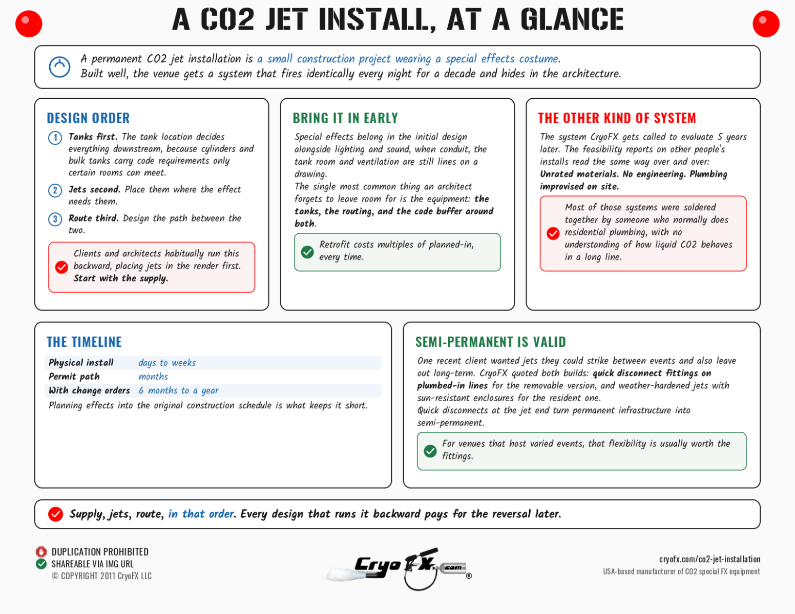
A permanent CO2 jet installation is a small construction project wearing a special effects costume. Built well, the venue gets a system that fires identically every night for a decade and hides in the architecture. The other kind is the system CryoFX gets called to evaluate 5 years later, and our feasibility reports on other people's installs read the same way over and over: unrated materials, no engineering, and plumbing improvised on site. What follows is the right order of operations, from first sketch to signed-off inspection.
Design order: tanks, jets, route
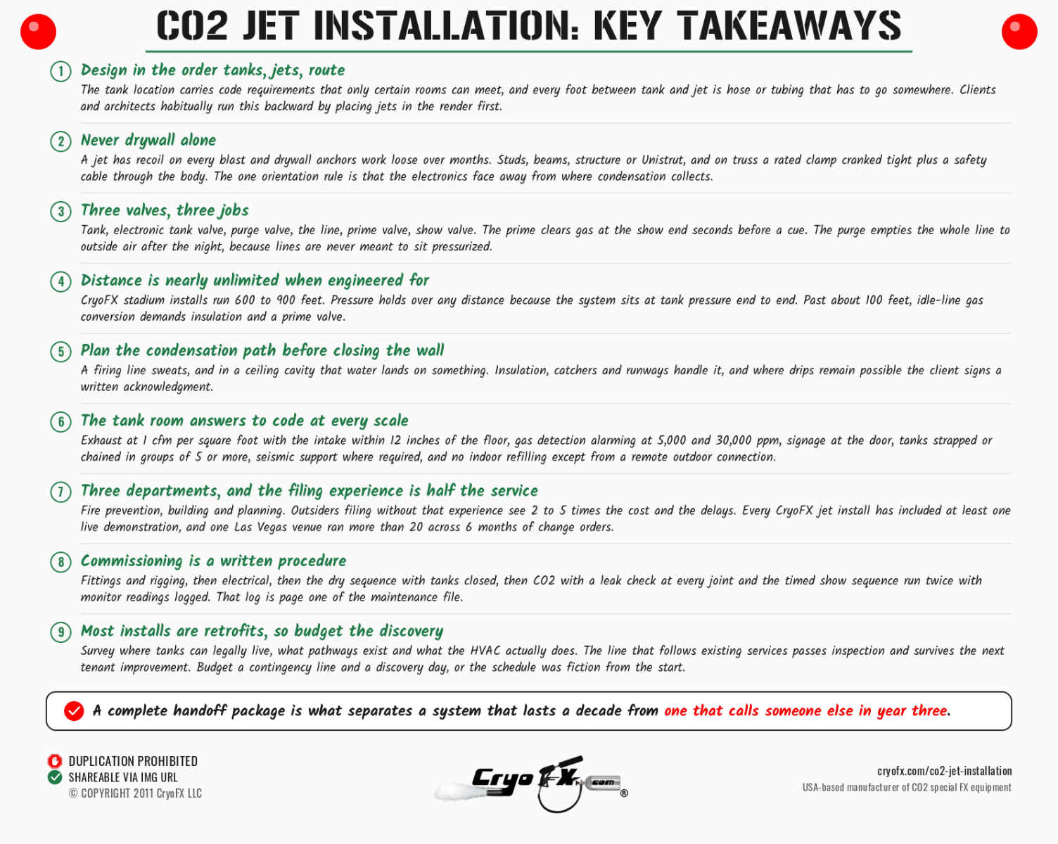
Start where the CO2 lives. The tank location decides everything downstream, because cylinders and bulk tanks carry code requirements (ventilation, monitoring, strapping, access) that only certain rooms can meet, and because every foot between tank and jet is hose or tubing that has to route somewhere. Then place the jets where the effect needs them. Then design the route between the two. Clients and architects habitually run this backward, placing jets in the render first. Start with the supply, and the rest of the design follows.
And bring the whole conversation in early. Special effects belong in the initial design alongside lighting and sound, when conduit, the tank room, and ventilation are still lines on a drawing. The single most common thing an architect forgets to leave room for is our equipment: the tanks, the routing, and the code buffer around both. Retrofit costs multiples of planned-in, every time.
Mounting
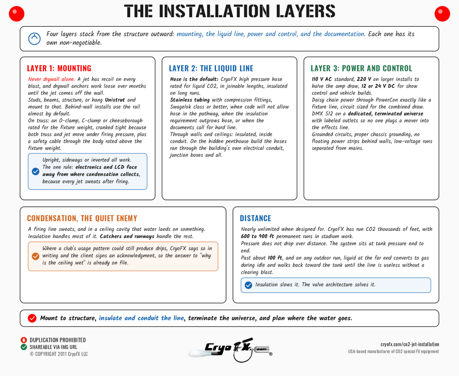
Never drywall alone. A jet has recoil on every blast, and drywall anchors work loose over months until the jet comes off the wall. Mount to studs, beams, or structure, or hang Unistrut and mount to that; behind-wall installs use the rail almost by default. On truss, use an O-clamp, C-clamp, or cheeseborough rated for the fixture weight, cranked tight because both truss and jet move under firing pressure, plus a safety cable through the jet body rated above the fixture weight, standard rigging practice for any 40 lb fixture. Jets mount upright, sideways, or inverted; festivals fly them upside down constantly. The one orientation rule: the electronics and LCD face away from wherever condensation collects, because every jet sweats after firing.
Semi-permanent is its own valid answer. One recent client wanted jets they could strike between events and also leave out long-term; we quoted both builds, quick disconnect fittings on plumbed-in lines for the removable version, and weather-hardened jets with sun-resistant enclosures for the resident version. Quick disconnects at the jet end turn a permanent infrastructure into a semi-permanent one, and for venues that host varied events, that flexibility is usually worth the fittings.
Routing the liquid line
Hose is the default: CryoFX high pressure hose rated for liquid CO2, in joinable lengths, insulated on long runs. The move to stainless steel tubing with compression fittings (Swagelok class or better) happens when code won't allow hose in the pathway, when the insulation requirement outgrows what hose carries, or when the project's design-build documents call for hard line; the tubing spec (diameter, length, fitting count) comes out of the engineering for that specific system.
Through walls and ceilings, lines run insulated and inside conduit, plastic or PVC for hose bundles, and on the hidden penthouse build the hoses ran through the same electrical conduit as the building's wiring, junction boxes and all, indistinguishable from the electrical services around them.
Condensation is the quiet enemy of enclosed routing. A firing line sweats, and in a ceiling cavity that water lands on something. Insulation handles most of it; catchers and runways handle the rest; and where a club's usage pattern could still produce drips, we say so in writing and the client signs an acknowledgment of the condition, so the answer to "why is the ceiling wet" is already on file.
Distance is nearly unlimited when designed for. CryoFX has run CO2 thousands of feet, with 600 to 900 foot permanent runs in stadium work. Pressure doesn't drop over distance (the system sits at tank pressure end to end), but temperature behavior changes: past about 100 feet, and on any outdoor run, liquid at the far end converts to gas during idle periods, and the gas converts its neighbors, walking back toward the tank until the line is useless without a clearing blast. Insulation slows it; the valve architecture below solves it.
Show, prime, and purge valves
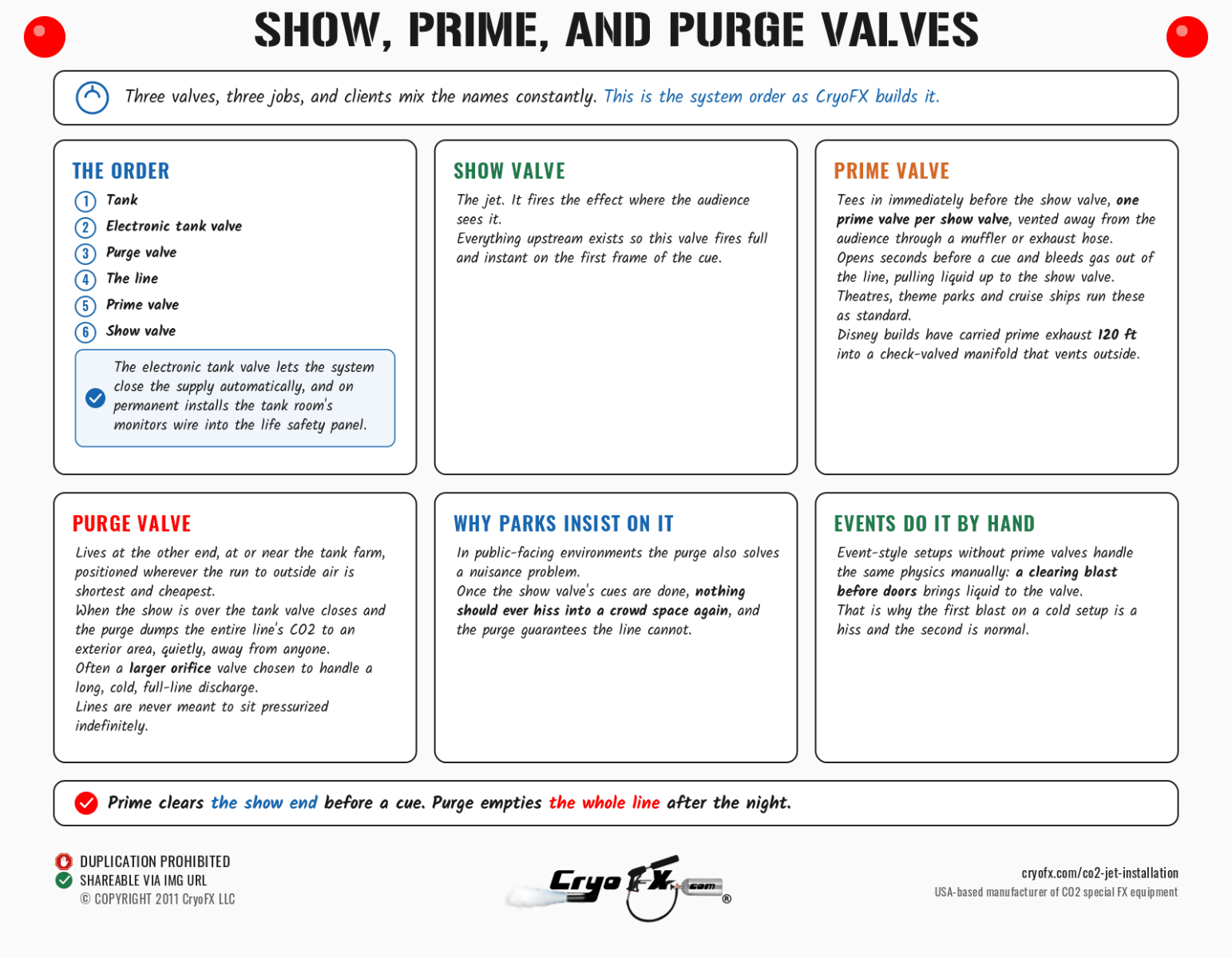
Three valves, three jobs, and clients mix the names constantly, so here is the system order as CryoFX builds it: tank, electronic tank valve, purge valve, the line, prime valve, show valve.
The show valve is the jet, firing the effect where the audience sees it.
The prime valve tees in immediately before the show valve, one prime valve per show valve, vented away from the audience through a muffler or exhaust hose. It opens seconds before a cue and bleeds the gas out of the line, pulling liquid up to the show valve so the cue fires full and instant. Theatres, theme parks, and cruise ships run these as standard; Disney builds have carried prime exhaust 120 feet into a check-valved manifold that vents outside.
The purge valve lives at the other end, at or near the tank farm, positioned wherever the run to outside air is shortest and cheapest. When the show is over, the tank valve closes and the purge valve dumps the entire line's CO2 to an exterior area, quietly, away from anyone, because lines are never meant to sit pressurized indefinitely. It's often a larger-orifice valve chosen to handle a long, cold, full-line discharge. In public-facing environments like theme parks, the purge also solves a nuisance problem: once the show valve's cues are done, nothing should ever hiss into a crowd space again, and the purge guarantees the line can't.
Event-style setups without prime valves handle the same physics manually: a clearing blast before doors brings liquid to the valve.
Power, control, and grounding
Each jet position needs power matched to the unit: 110 V AC standard, 220 V on larger installs to halve the amp draw, or 12/24 V DC where a show controller or vehicle build calls for it. Daisy chain power through PowerCon runs down a jet line exactly like a fixture line, with the circuit sized for the combined draw. Control runs DMX 512 on a dedicated, terminated universe reserved for special effects, with labeled outlets so no one plugs a mover into the effects line, or wireless with hard-coded timers where the operator is a venue manager rather than an LD.
Electrical work follows the same practices as any fixture install: grounded circuits, proper grounding on every chassis, no floating power strips daisy-chained behind walls, and low-voltage runs separated from mains. All of it lands on the low-voltage and electrical sheets of the permit drawings.
The tank room
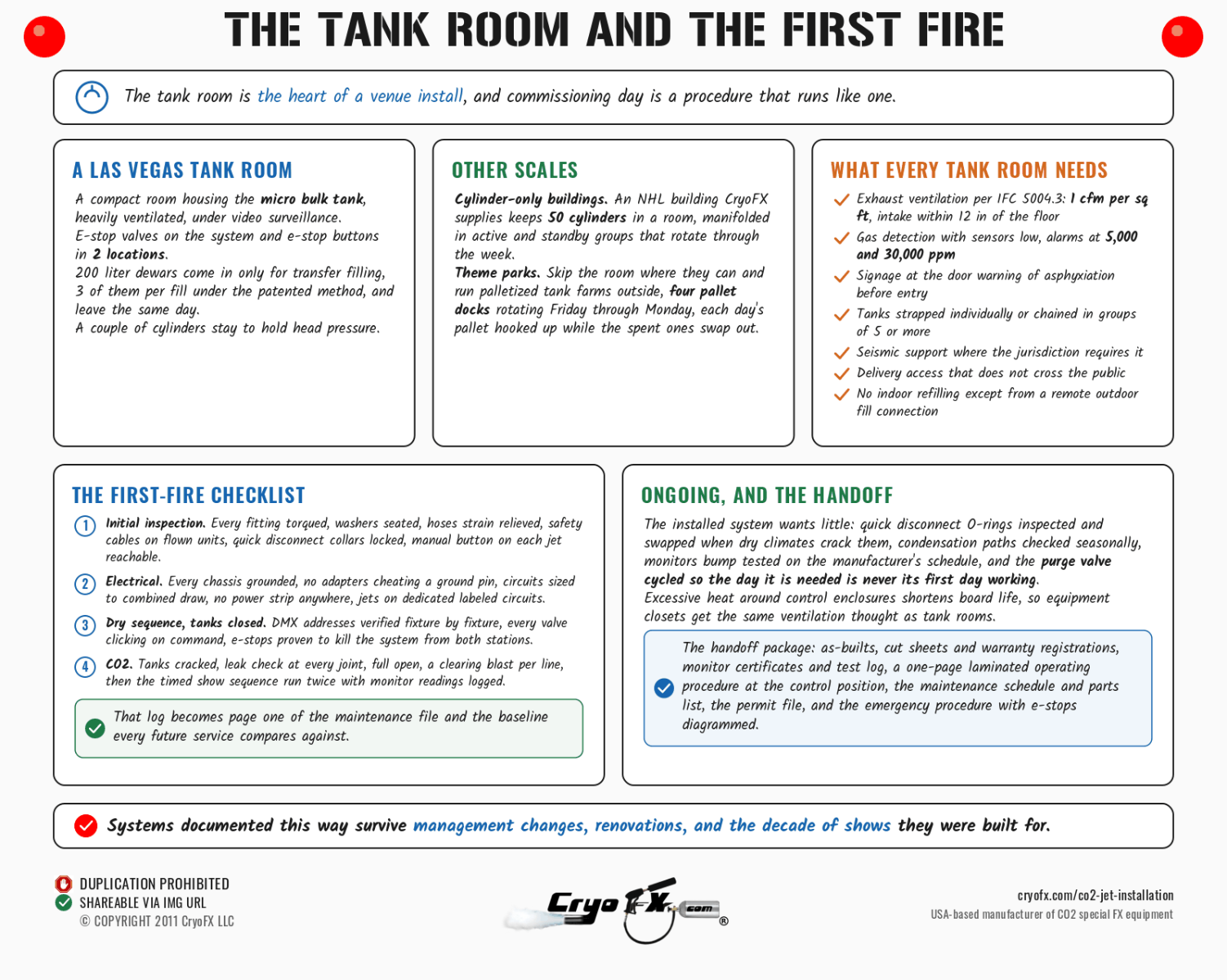
The heart of a venue install. A CryoFX tank room in Las Vegas runs like this: a compact room housing the micro bulk tank, heavily ventilated, under video surveillance, with e-stop valves on the system and e-stop buttons in 2 locations. Two-hundred-liter dewars come in only for transfer filling (3 of them fill the bulk tank under our patented method) and leave the same day; a couple of cylinders stay to hold head pressure.
Cylinder-only buildings run the same logic at different scale: an NHL building we supply keeps 50 cylinders in a room, manifolded in active and standby groups that rotate through the week. Theme parks skip the room entirely where they can and run palletized tank farms outside, four pallet docks rotating Friday through Monday, each day's pallet hooked up while the spent ones swap out.
Whatever the scale: exhaust ventilation per IFC 5004.3 (1 cfm per square foot, intake within 12 inches of the floor), gas detection with sensors low and alarms at 5,000 and 30,000 ppm, signage at the door (the code's required wording warns of asphyxiation before entry), tanks strapped individually or chained in groups of 5 or more, seismic support where the jurisdiction requires it, delivery access that doesn't cross the public, and no indoor refilling except from a remote outdoor fill connection.
[CALCULATOR BLOCK: CO2 ROOM SAFETY CONCENTRATION ESTIMATOR HERE, for tank room and venue sizing]
[CALCULATOR BLOCK: CO2 CONVERSION CALCULATOR HERE, lb to cubic feet for the permit application's aggregate quantity line]
Documentation, departments, and the timeline
A permanent install answers to three departments: fire prevention, building, and planning, and knowing how to navigate all three is half the service. Outsiders filing without that experience see 2 to 5 times the cost and the delays. The package CryoFX Designs produces: stamped mechanical, electrical, and plumbing drawings, a low-voltage plan covering DMX and the CO2 alarm, equipment cut sheets, the MSDS, the monitoring plan, and the fire-department-specific items the permit page details, including total aggregate CO2, room volumes, piping diagrams, venting details, and seismic support per IFC 5307.4.1.
Inspections are staged, and on jet installs the demonstrations are real: every install we've done has included at least one, and one Las Vegas venue ran more than 20 demonstrations across 6 months of change orders, testing sensors at specific CO2 concentrations until the fire inspectors signed off on what they themselves called one of the most sophisticated systems ever built. Budget months for a clean install's permits, and longer when change orders arrive. Warranty claims and labor warranty terms on the equipment side stay intact when the install follows the book, which is one more argument for following it.
The full technical foundation for everything above sits in the CO2 jet installation and systems guide on the pillar, with hose specifications detailed on the CO2 jet hose page. Equipment for installs, from split-body jets to valves, monitors, and hose, is on the CryoFX catalogue under CO2 jets for sale, and CryoFX Designs handles the drawings, permits, and build at whatever level of involvement the project needs.
Commissioning: the first-fire checklist
The day the system first fires is a procedure, and it runs like one. Initial inspection first: every fitting torqued, washers seated, hoses strain-relieved, safety cables on flown units, quick disconnect collars locked, and the manual button on each jet confirmed reachable. Electrical second: every chassis grounded through its 3-prong plug or hardwire, no adapters cheating a ground pin, circuits sized to the combined draw, and no power strip anywhere in a permanent system; jets land on dedicated, labeled circuits.
Then the dry sequence with tanks closed: DMX addresses verified fixture by fixture, every valve clicking on command, e-stops proven to kill the system from both stations. Then CO2: tanks cracked, leak check with soap and water or the handheld detector at every joint, full open, a clearing blast per line, and the timed show sequence run twice while the monitor readings get logged. That log becomes page one of the maintenance file and the baseline every future service compares against.
Ongoing, the installed system wants little: quick disconnect O-rings inspected and swapped when dry climates crack them, condensation paths checked seasonally, monitors bump-tested on the manufacturer's schedule, and the purge valve cycled so the day it's needed is never its first day working.
Excessive heat around control enclosures shortens board life, so equipment closets get the same ventilation thought as tank rooms. Following the book here also keeps warranty claims clean: the labor warranty on CryoFX equipment covers defects, and an install log that shows rated parts and procedure is what separates a covered claim from an argument.
The retrofit reality
Most installs are retrofits into buildings that never planned for them, and the playbook adapts. Survey first: where can tanks legally live, what pathways exist (existing conduit, chases, drop ceilings), and what the HVAC actually does, single-pass or recirculating, because the answer decides the monitoring design. Route second, accepting that the shortest line rarely wins; the line that follows existing services is the one that passes inspection and survives the next tenant improvement.
Stage the work third around the venue's calendar, since a club that closes Sunday to Wednesday gets its install in those windows, and pressure testing happens before the Thursday staff arrives. Retrofits also surface the building's history: undocumented wiring, dead conduit, and the occasional previous "cryo system" that our feasibility reports were written about. Budget a contingency line and a discovery day, and the retrofit lands on schedule; skip both and the schedule was fiction from the start.
What the finished system hands the venue
Commissioning day ends with a handoff package, and a complete one carries: the as-built drawings marked with every deviation from the design set, the equipment cut sheets and warranty registrations, the monitor certificates and their test log, the operating procedure written for the venue's actual staff (one page, laminated, at the control position), the maintenance schedule with the service intervals and the parts list, the permit file with every approval and inspection record, and the emergency procedure with the e-stop locations diagrammed.
The venue's engineer gets a walkthrough, the operating staff get their training session, and the fire department's file matches the venue's file page for page. Systems documented this way survive management changes, renovations, and the decade of shows they were built for; systems without the package call us in year three asking what the previous team installed, and the feasibility study starts from zero.
Frequently asked questions
How do you install a CO2 jet permanently? Tanks first, jets second, route third: place the code-compliant tank location, mount the jets to structure, and run insulated hose or stainless tubing between them, with power and a dedicated DMX universe to each position, then permit and inspect. CryoFX Designs produces the stamped drawings and manages the process.
Can CO2 jets be mounted to a ceiling? Yes, to structure or Unistrut above the ceiling, never to drywall alone, with the electronics oriented away from condensation and the plume path clear of anything within the clearance distances.
Can CO2 jets be mounted on truss? Yes, with a rated O-clamp, C-clamp, or cheeseborough plus a safety cable through the jet body, the same rigging discipline as any flown fixture. Inverted mounting is routine.
Can CO2 lines run through walls? Yes, insulated and in conduit. CryoFX has routed hose through electrical conduit so cleanly that nothing in the room reveals a CO2 system exists. Plan the condensation path before closing the wall.
How far can a CO2 hose run? Thousands of feet when engineered for it; CryoFX's stadium installs run 600 to 900 feet. Pressure holds over any distance; past about 100 feet, idle-line gas conversion demands insulation and a prime valve.
What is a purge valve? The valve near the tank farm that empties the whole line to an outside area after the show, so lines never sit pressurized. It works alongside the prime valve, which clears gas at the show-valve end seconds before each cue.
What power do CO2 jets need? 110 V AC standard, 220 V on larger installs for lower amp draw, or 12/24 V DC for show control and vehicle builds, daisy-chained through PowerCon with properly grounded circuits.
Do I need a permit for a permanent CO2 jet installation? Yes, everywhere: building, fire, and electrical permits with stamped MEP drawings, monitoring plans, and staged inspections. Las Vegas installs also demonstrate the system live for fire inspectors, sometimes repeatedly.
How long does a CO2 jet installation take? The physical install is days to weeks. The permit path is months, and complex projects with change orders have run 6 months to a year. Planning effects into the original construction schedule is what keeps it short.
___
CryoFX® is the leading manufacturer, designer, and global supplier of CO2 special effects equipment and custom special effects systems
for Theme Parks, Sporting Arenas, Mega Nightclubs & Day Clubs , TV/FILM & large scale events & installs in any industry requiring Co2 Systems.
CryoFX LLC Global Headquarters • 3859 S Valley View Blvd, Suite 2, Las Vegas, NV 89103 • 1.855.527.9639
Updated - 09/06/2026.